1. Scheme description
The system is divided into three parts: front-end acquisition and monitoring subsystem, cloud subsystem and monitoring end analysis and alarm subsystem.
The whole system adopts the whole network digital control and monitoring architecture: the front-end acquisition and monitoring subsystem adopts the mobile infrared thermal imager module, equipped with intelligent terminals (mobile phones, flat panel, etc.), and transmits the collected data to the cloud subsystem through wireless or 4G signals, and the back-end (monitoring end analysis and alarm subsystem) completes the centralized preparation of the whole infrared temperature data through the monitoring server platform The functions of reading, control, management, storage, AI intelligent analysis, intelligent early warning and other functions can realize the centralized management of the whole infrared monitoring system.
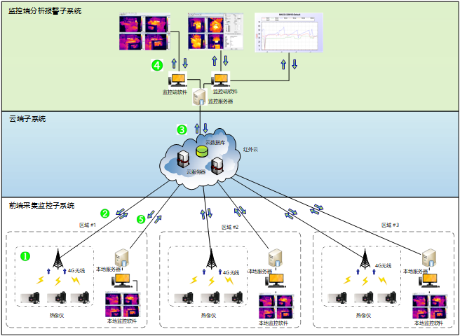
Figure 1 Schematic diagram of scheme system structure
2. Detailed introduction of the scheme
2.1 front end acquisition and monitoring subsystem
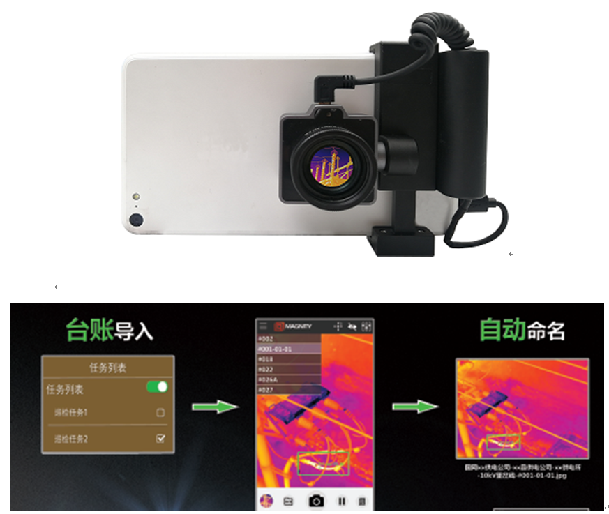
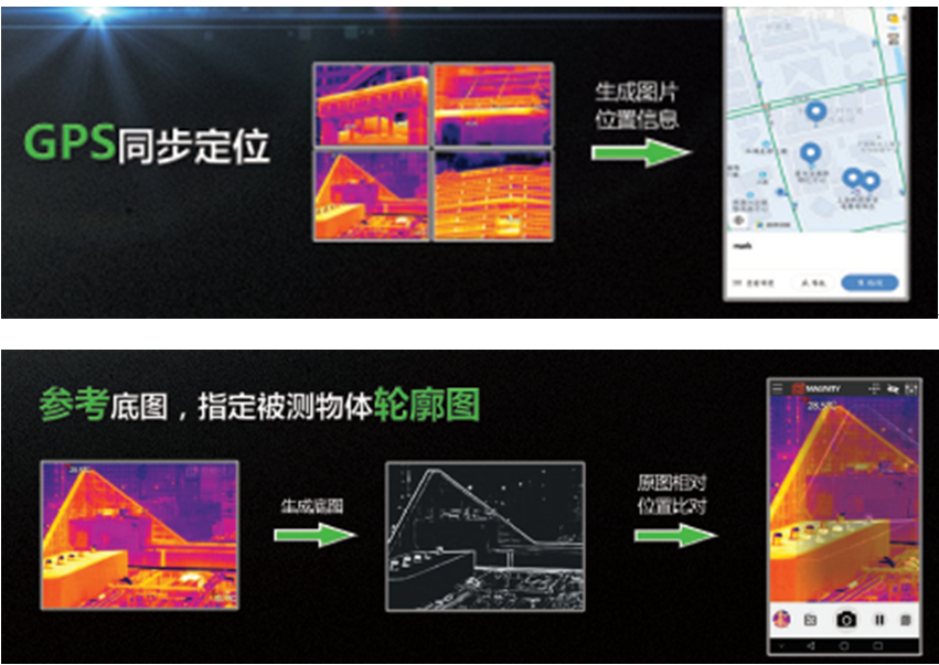
The front-end acquisition and monitoring subsystem is composed of mobile infrared thermal imager module, intelligent terminal (mobile phone, tablet, etc.) and terminal app, with simple structure and convenient use. At the same time, it has the functions of account import, automatic naming, GPS positioning, reference map, etc., and the app function is conducive to adding and expanding.
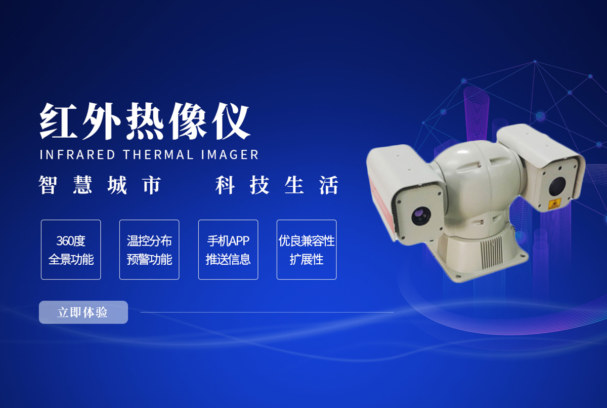
The mobile infrared thermal imager module adopts the new imported 640 * 480 / 384 * 288 detector to present infrared image and ensure accurate temperature measurement. At the same time, it adopts a new back clip design, is compatible with intelligent terminal equipment, and cooperates with exclusive app to ensure the accuracy, portability, ease of use and durability of the front-end acquisition equipment.
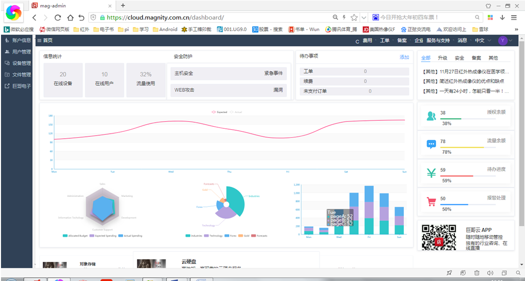
2.2 cloud subsystem
The cloud subsystem adopts the system architecture based on the Ubuntu system and cooperates with the server database to complete the infrared data collection, storage, intelligent analysis, intelligent warning, report forms and other work of each front terminal system, as well as the distribution of infrared data, flow monitoring, load balancing and other work.


2.3 monitoring terminal analysis and alarm subsystem
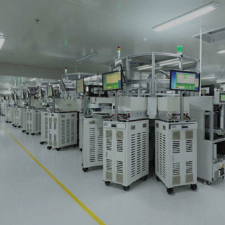
The block diagram of the analysis and alarm subsystem at the monitoring end is shown in the figure, which can be configured according to the actual needs, including control computer, network switch, control equipment (optical fiber transceiver, matrix controller, etc.). The field collected data is transmitted to the monitoring center through the transmission network. After the temperature data is processed by the server, it is displayed on the TV wall and monitor in real time to meet the needs of real-time monitoring of the scene picture and temperature.
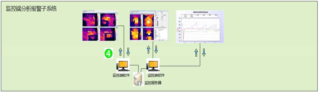
Structure diagram of monitoring terminal analysis and alarm subsystem
The local area network or optical fiber ring network can be used to connect the on-site monitoring unit and the main control communication building. The image information is transmitted in full digital mode to avoid the interference of electromagnetic field in the field.
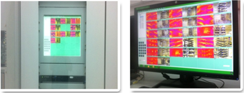
Schematic diagram of monitoring center
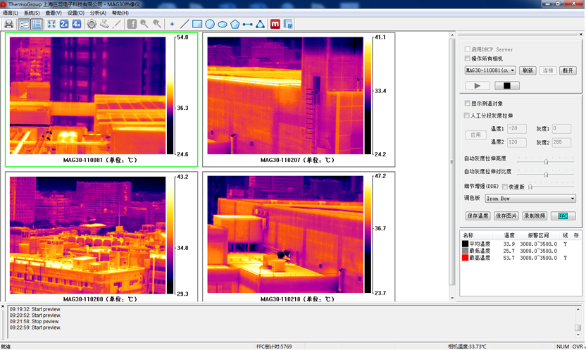
Monitoring cluster software thermogroup software interface
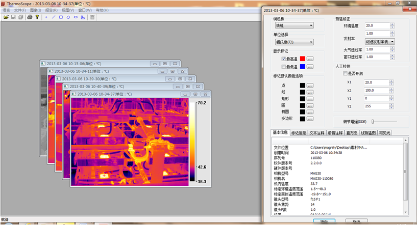
Thermoscope software interface of offline analysis software
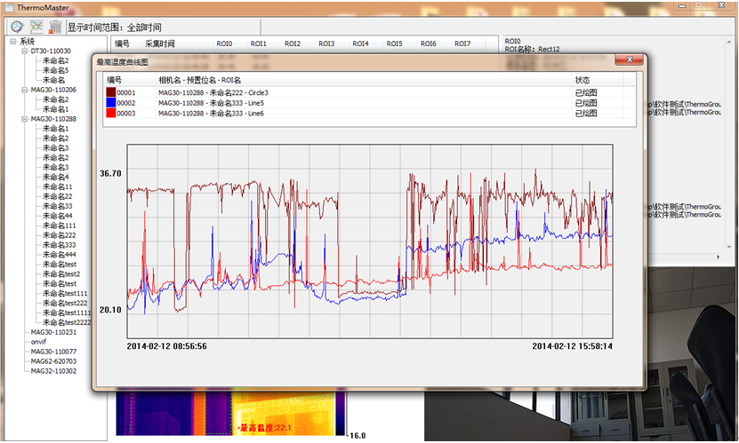
Analysis curve of temperature change


wap site
